00-HelloWord
├── hello.c
├── hello.ld
├── Makefile
├── reg.h
└── startup.c
- 這個 helloworld 要做到從 USART2 輸出 “Hello World!”
reg.h 定義了各個 register 的 memory address, stm32的 memory map 參考這邊[1]
這個部份需要以下3個的 memory address
- Reset and Clock Control
- RCC
- 0x4002 1000
- RCC_APB2ENR (APB2 peripheral clock enable register)
- 0x4002 1000 + 0x18
- RCC_APB1ENR (APB1 peripheral clock enable register)
- 0x4002 1000 + 0x1C
- RCC
- GPIO
- GPIOA
- 0x4001 0800
- GPIOA
- USART2
- USART2
- 0x4000 4400
- USART2
hello.c 中,main function 共設定3了個部份
|
1 2 3 4 5 6 7 8 9 |
*(RCC_APB2ENR) |= (uint32_t) (0x00000001 | 0x00000004); *(RCC_APB1ENR) |= (uint32_t) (0x00020000); /* USART2 Configuration */ *(GPIOA_CRL) = 0x00004B00; *(GPIOA_CRH) = 0x44444444; *(USART2_CR1) = 0x0000000C; *(USART2_CR1) |= 0x2000; |
在一個一個拆開來看前,先看一下 system architechture
 |
| [1] p.38 |
 |
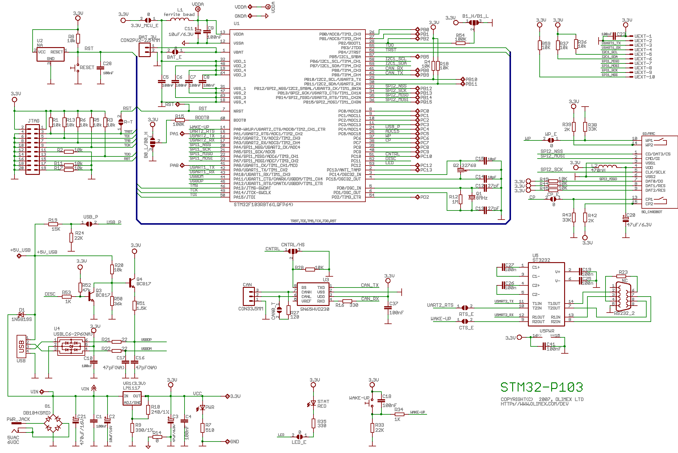
| STM32-p103 layout [2] |
先在上面的 layout 看到,USART2_TX 用 PA2, USART2_RX 用 PA3,因此在GPIO_CRL跟GPIO_CRH的時候要設定CNF2/3與MODE2/3的部份。
首先要設定有關 APB clock 的部份,GPIOA在APB2,USART2在APB1,分別在其 register 設定為 enable。
|
1 2 |
*(RCC_APB2ENR) |= (uint32_t) (0x00000001 | 0x00000004); *(RCC_APB1ENR) |= (uint32_t) (0x00020000); |
第一行設定RCC_ABP2ENR的值為0x5,enable IOPA與AFIO的部份。[3]
第二行設定RCC_ABP1ENR的值為0x20000, enable USART2 的部份。 [4]
接著先設定 GPIOA 的部份
|
1 2 3 |
*(GPIOA_CRL) = 0x00004B00; *(GPIOA_CRH) = 0x44444444; |
最後設定 USART2 的部份
|
1 2 3 |
*(USART2_CR1) = 0x0000000C; *(USART2_CR1) |= 0x2000; |
測驗
Reference
[1] RM0008 Reference manual STM32F101xx, STM32F102xx, STM32F103xx, STM32F105xx and STM32F107xx advanced ARM-based 32-bit MCUs
, http://www.keil.com/dd/docs/datashts/st/stm32f10xxx.pdf, p.41
[3] RM0008 Reference 6.3.7 APB2 peripheral clock enable register (RCC_APB2ENR), p.95
[4] RM0008 Reference 6.3.8 APB1 peripheral clock enable register (RCC_APB1ENR), p.97
Leave a Reply